
 The 2000 engine (and its 2200 derivative) has often been cast into the shadow of the Rover V8. In some circles, it has also garnered something of an unfair reputation for being slow, rough and unrefined. Clearly, a 2-litre, 4-cylinder engine could never match a small-block V8 for outright power or smoothness, but the 2000 is far from an unsophisticated piece of kit. In fact, like the rest of P6, it is a remarkably advanced and intelligently engineered design.
By contrast to the V8, the 2000/2200 is a very “highly stressed” engine. Coupled to its advanced design, in peak health this makes for a very efficient power unit capable of extracting a large amount of power from a deceptively small displacement – 114bhp from 1978cc in the 2000 TC vs 144bhp from the 3528cc V8 (a difference of just 30bhp over an engine nearly twice the size and marginally heavier). But because of this high running stress, after forty or fifty years with nothing more than an annual oil change, the 2000 engine begins to develop running issues that adversely affect performance, smoothness and economy. The most familiar of these for most owners will be tinkling, rattling timing chains, a lumpy and inconsistent idle, and a narrow power band with broad flat spots in acceleration.
The good news is that these issues aren’t caused by any fundamental weaknesses or bad design, and rarely cause irreversible internal damage. They are the result of worn tolerances in consumable components. Such is the accuracy required to set a 2000 or 2200 engine up properly that variations down to hundredths or thousandths of an inch are enough to turn a sharp and smooth 2000 into a grumbling bag of spanners.
Better news still is that all of these worn components and slack tolerances can be replaced and reset easily with the engine in situ. In this two-part article, we will be showing you how, armed with only a few basic hand tools and some replacement components, you can undertake and complete two major overhaul procedures on your four-cylinder engine to help restore performance closer to the factory standard in just a weekend – and all without removing any significant parts from the engine at all!
Part 1 – Cylinder Head
Being an overhead cam engine design, the cylinder head is occupied in governing all of the variables associated with the opening and closing of the valves. This means the valve clearances, opening events and timing.
Start with a general health inspection
There is little point making adjustments to your cylinder head until you have ascertained what state of health it is in.
Once you have removed the cam cover from its three retaining studs, measure your valve clearances. There is no ‘rule of 9’ with an OHC engine, simply rotate the engine by hand until each cam is pointing straight upwards and measure the gap underneath between the bucket and rear of the cam with a set of feeler gauges using the ‘one-over’ method. If you think the gap is 12, try 13. If 13 doesn’t fit, you know it’s 12. If it does fit, try 14, etc.
The engine should be stone cold (i.e. left overnight). The factory clearance is between 8-10 thou for inlet valves and 13-15 thou for exhausts.
Inlet valves should not have changed very much over the years so if they are substantially tighter (ie, less than 6 thou), you should think about removing the head to investigate the state of the seats and valves. The exhaust valves are likely to have receded a fair amount. Expert opinion differs as to whether the seats are hard enough to tolerate modern unleaded fuel as standard if your engine is set up correctly, but widespread experience suggests they do recede. If the seats are hard enough, recession may be due to years of incorrectly set ignition timing or carburettors causing pinking and lean running at speed, super-heating the valve seats and damaging them. Whatever the cause, four-cylinders are known to burn-out exhaust valves with remarkable ease if the tolerances are too tight. Any tighter than 8 thou should be rectified with immediate effect to prevent lasting damage to the cam, valve and bucket tappet.
It is rare that a tolerance would be greater than the factory standard, but if your gaps have been adjusted in the past, it if possible they may be bigger. If this is the case, no damage will be caused but the engine will be much more rattly than normal, and breathing may be fractionally poorer owing to smaller and shorter valve events.
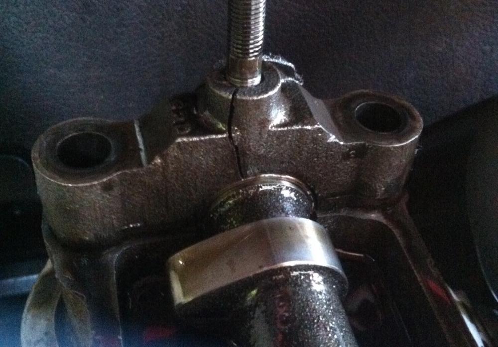
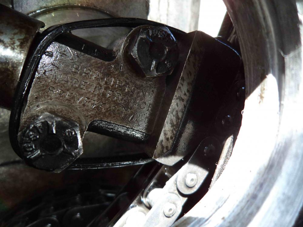
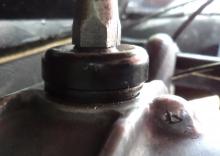
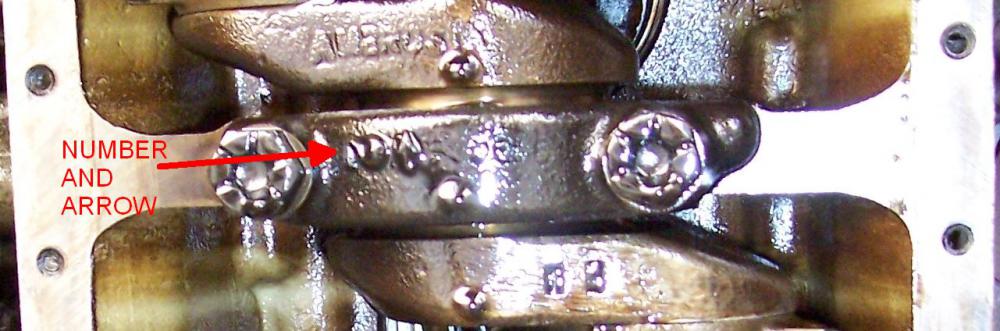
Inspect your bearing caps. Particularly the ones containing the studs for the cam cover. If the cover is tightened down too much, it can crack the cast iron bearing caps. If cracked (as shown below), they should be replaced to prevent failure (and potential camshaft breakage) in future.
Next inspect your cam. You are looking for any signs of wear, damage or scoring to the lobes and backs. The camshafts are case hardened, so if the tough top layer has been ground away they will very quickly wear themselves away further.
Inspect the reservoirs around the bucket tappets. Do they contain enough oil to just cover the top surface of the bucket when it is depressed by the cam? Is the oil clean and, crucially, is it free from crud and deposits? The rearmost reservoir will probably be the fullest, but if it is not, reach down the back of the engine to the joint of the cylinder head and block. Is there a multitude of oil on top of the bell housing? If so, the O ring in the cylinder head gasket is likely to have failed meaning your camshaft is being starved oil.
At this stage, you need to determine whether the head needs to be removed. If the O-ring has failed or your valve clearances need to be reset, you have little other option. Valve clearances are set by adding or removing shims and cannot be adjusted without at least removing the cam and head bolts. Removing the head is a complex and involved process. If you need to go down this route, you should refer to the workshop manual for the full process. Alternatively, you can contact a member of the technical team who will be happy to provide detailed information. The information in this article is intented to inform you of when it might be critical to undertake major cylinder head work – something not covered in the workshop manual – but the scope of the article is merely to outline the improvements that can be made to a good running engine in situ to improve performance and refinement.
Resetting the cam timing
Once you’ve inspected the head and are satisfied with its health, look at the cam timing.
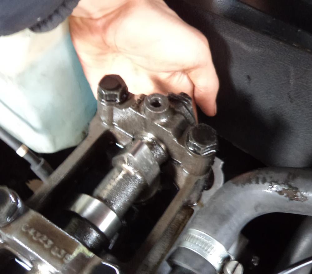
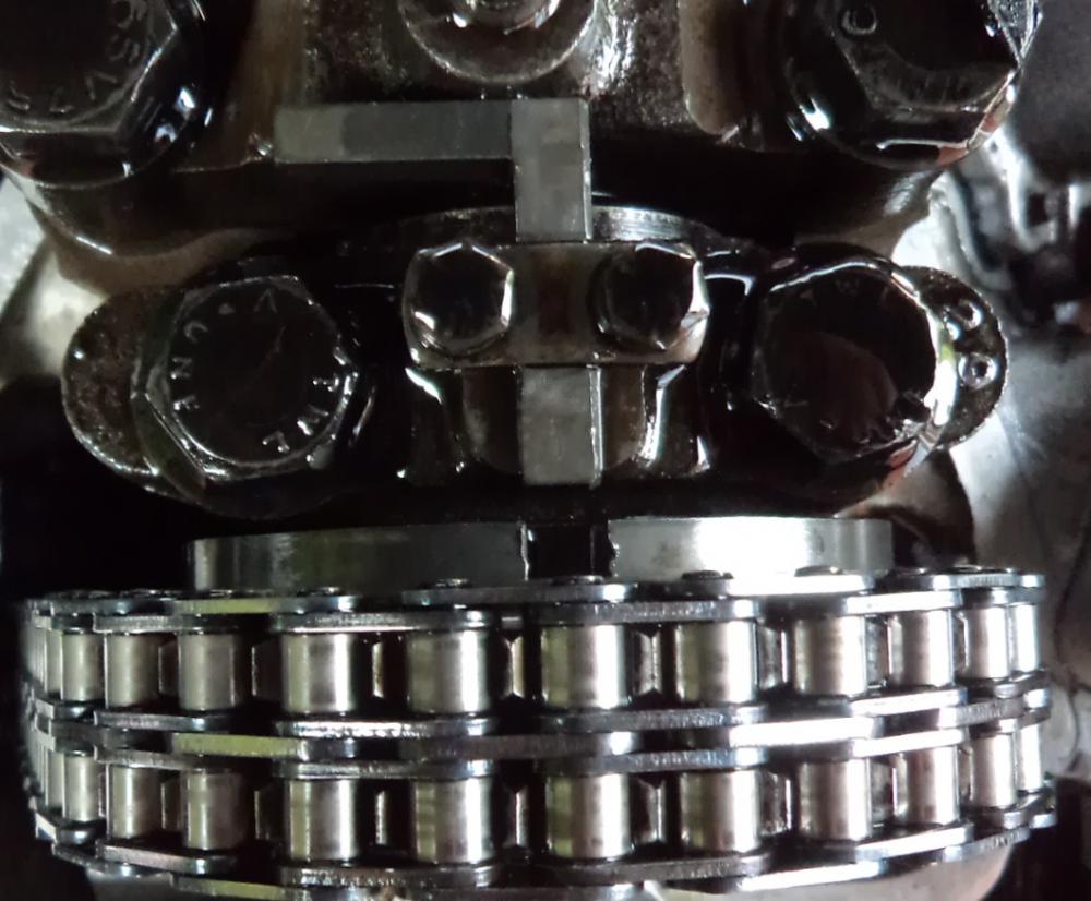
The top chain wheel is ring with a series of fine teeth on the inside edge. This is sandwiched between the flange on the end of the camshaft, and the separate centre of the chain wheel which meshes with those teeth to hold it in position. By slackening the bolts on the centre part of the wheel, you can unmesh the fine teeth allowing the camshaft to be freely rotated. When it is in the correct position, you simply push the centre back into engagement with the teeth and tighten the bolts up. The high number of small teeth allows a remarkably fine range of adjustment, and this method neatly avoids disturbing the poorly accessible chains and tensioners, and minimises the number of components to be disturbed.
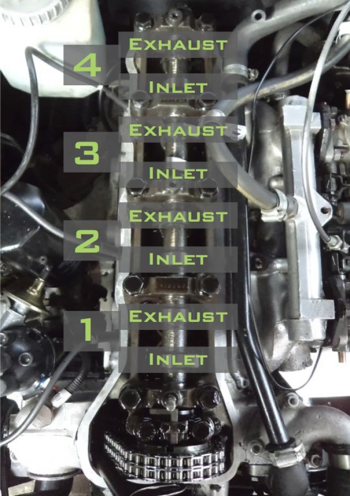
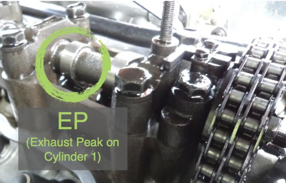
Start by pinning the engine in the ‘EP’ (exhaust peak) position. This is can be found by rotating the engine so that the exhaust of cylinder 1 (second cam lobe from the front of the engine) is pointing downwards and the valve is fully open.
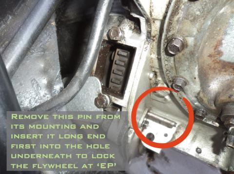
Remove the inspection cover on the bell housing and look for the ‘EP’ mark. Insert the pin on the engine rear plate through the hole and budge the engine back and forth until it slips through the hole in the flywheel, pinning the engine in place.
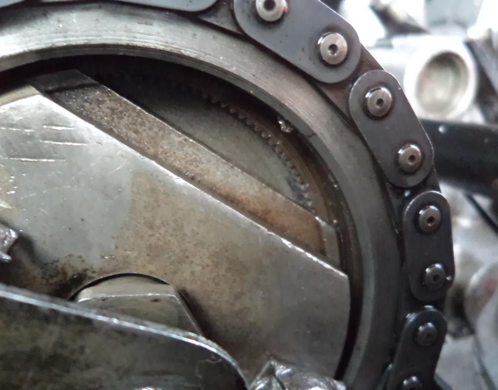
Now look at the notch on the flange of the camshaft. Does it line up with the locking tab? The chances are high it will be a little to the left. Click the image below to enlarge.
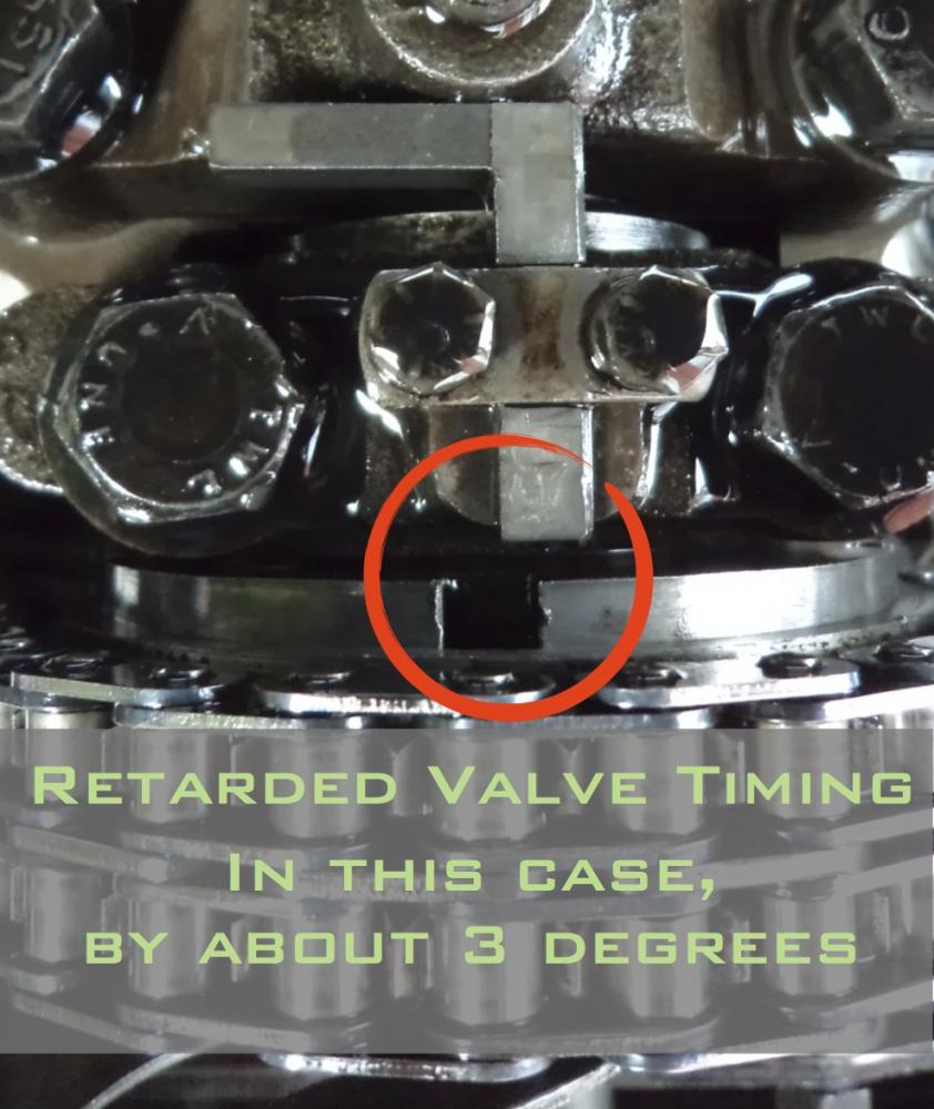
This is a result of the chains having stretched in operation, and probably occurred in the first few thousand miles of the car’s life. No damage is likely to have been inflicted by this. It simply means your valve timing is a few degrees retarded from the optimum position. This is one of the principal causes of lumpy tickover, poor pick-up and acceleration, and a lack of top-end go. Most engines – especially TCs – should rev cleanly and easily to at least 4000 rpm in a low gear before the power curve flattens off.
Reset the cam timing.
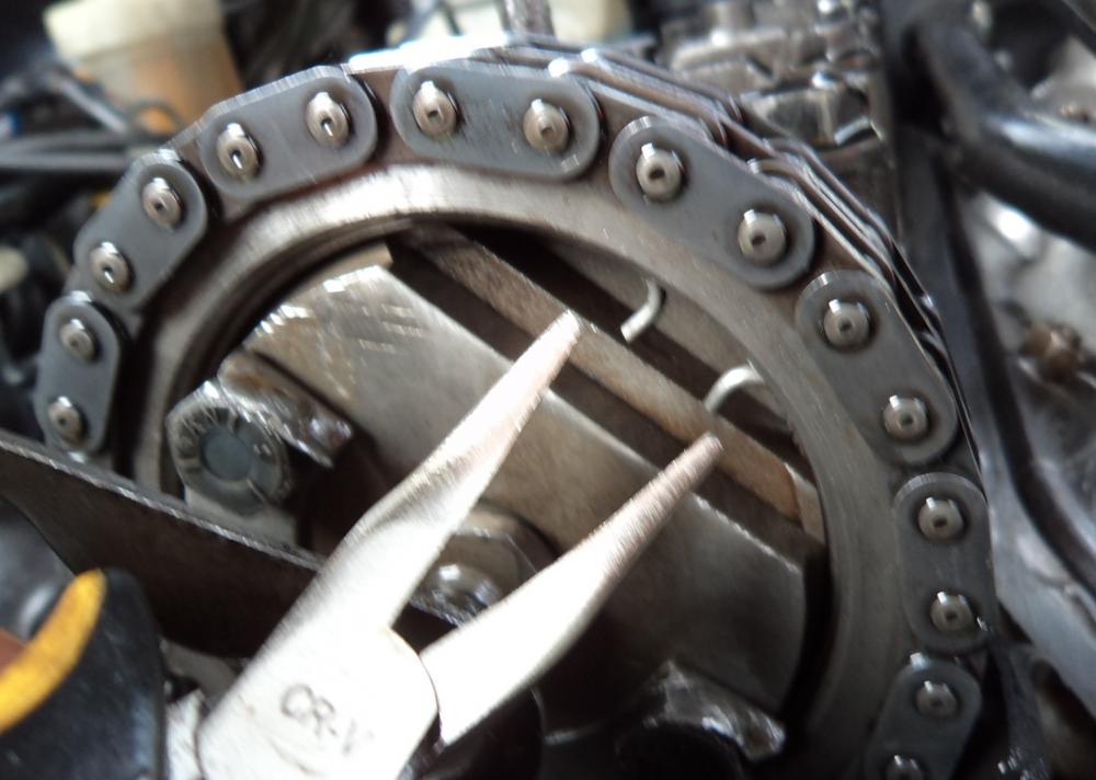
1. Extract the circlip from the top chain wheel with a pair of long nose pliers. [Fig 1, below]
2. Knock back the locking tabs on the two securing bolts holding the chain wheel to the camshaft end flange. [Fig 2].
3. Undo the two bolts until they are held in by two or three turns only, but do not remove them in any circumstances.
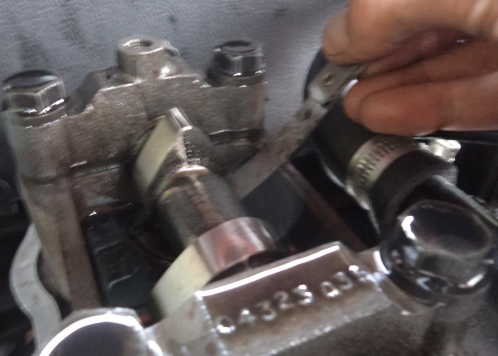
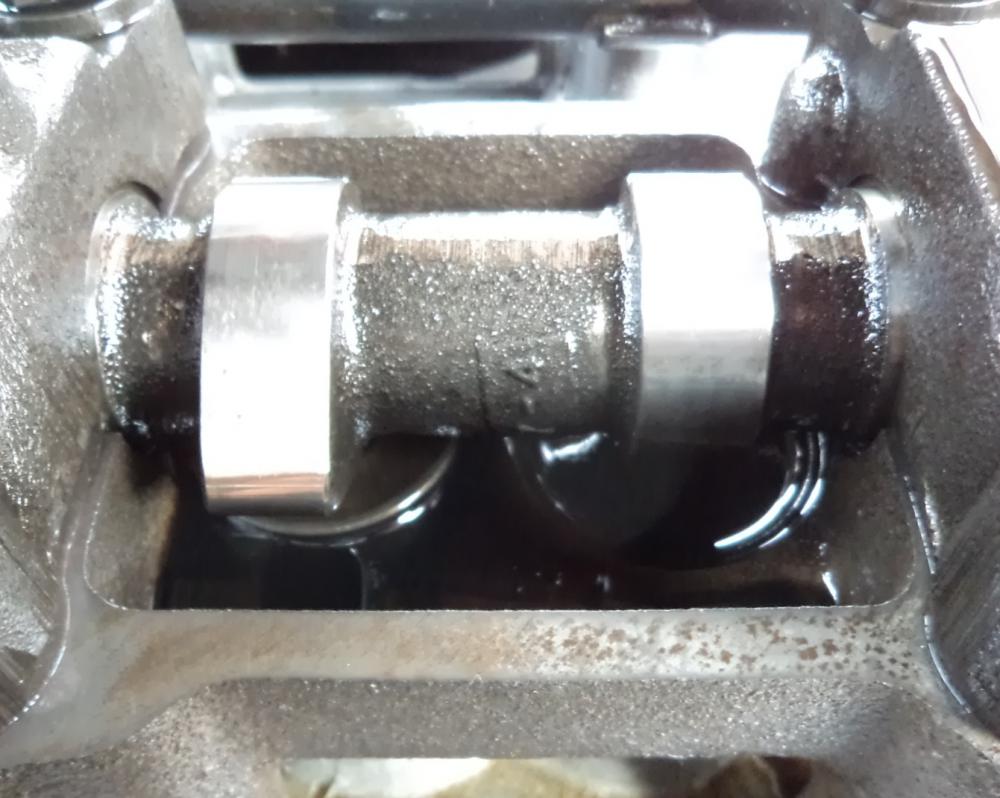
4. Gently push on the chainwheel to ensure it stays mated with the end of the camshaft whilst simultaneously pulling the central stud of the chainwheel to disengage the fine teeth of the vernier adjustment within the chainwheel. [Fig 3 & Fig 4]
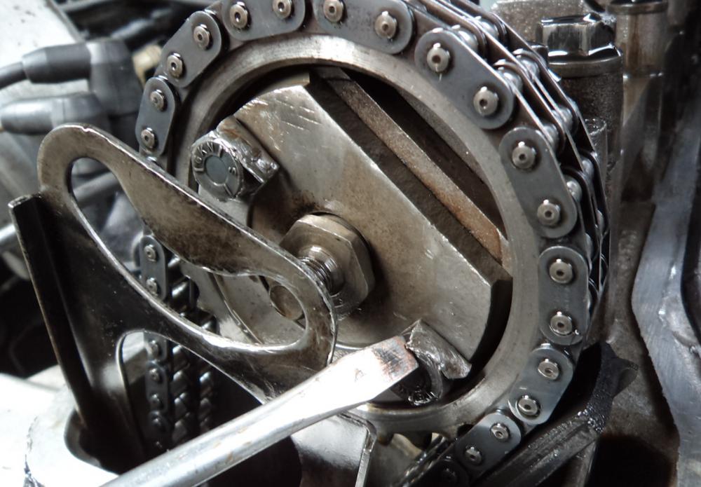
5. Using a suitable C-spanner or blunt drift, gently rotate the camshaft round until the slot in the flange lines up with the locking pin. [Fig 5]. If need be, remove the securing strap on the locking pin and insert it into the flange slot to hold the cam in position.
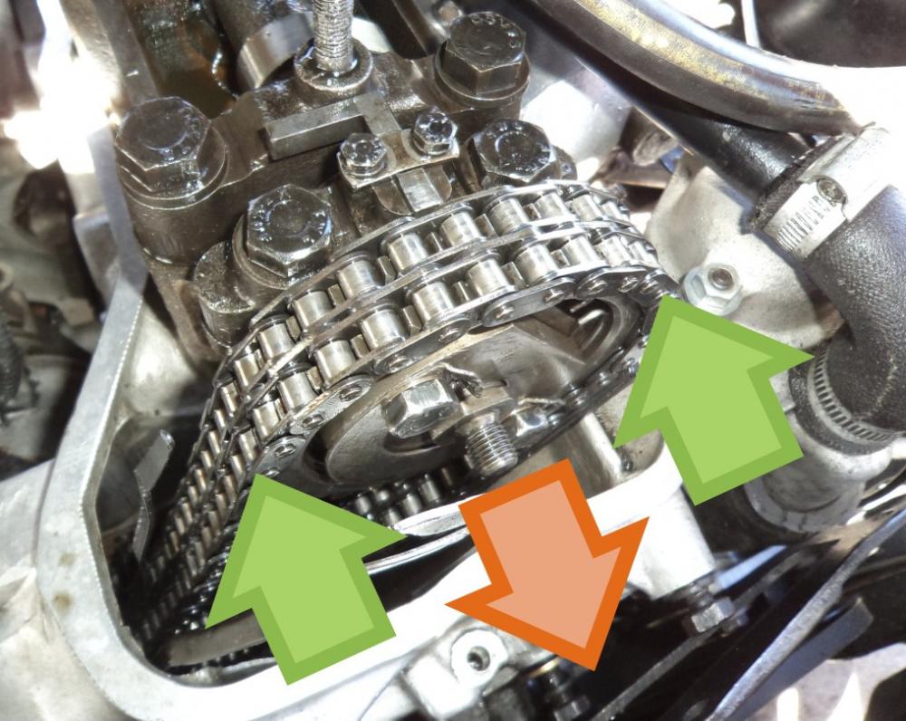
6. Ensure the chainwheel is still pushed home onto the end of the flange. Using your hands, push the left side of the chains inwards with some force to ensure the driven side of the chains is tight. Then simply push the centre of the chainwheel back in place until the teeth mesh and the centre is in square.
7. Retighten the two bolts to 10 lbft or ‘arm tight’, and reinsert the circlip.
8. Remove the two locking pins (bell housing and camshaft flange) and rotate the engine by hand to check valve collision does not occur. Restore the engine to the EP position again and recheck the camshaft is now in the right position when Exhaust Valve 1 is fully open. The slot and locking tab should now line up.
Click images to enlarge
Note on chain tensioner: The top chain tensioner does not need to be released or removed when resetting the cam timing as described in the article. The workshop manual states that it should be released, but this is in the context of a larger dismantling and reassembly of the cylinder head. Provided the top chain wheel is not removed from the flange of the camshaft, the chain and tensioner is not affected. The method outlined in the article is a based on the experience of several members knowledgable in rebuilding the four-cylinder, and involves releasing the teeth of the vernier adjuster so that the camshaft can be freely rotated to its appropriate position without disturbing the chains.
Hints & Tips
Top chain tensioner
 One symptom of rattly timing chains can be a blocked chain tensioner. The easiest and safest way to remove the top chain tensioner if to prise away the alloy blanking plug on the cylinder head shoulder and tie a cable tie around the tensioner and pad assembly. It can then be extracted as one unit through the window for dismantling and cleaning. Put another tie around it when reinserting it. It is possible to retract the tensioners, but the mechanisms may be worn after many years’ service and it is not worth risking the pain of the springs jettisoning down into the sump!
While you are there, remove the nylon oil strainer beneath the banjo union on top and clean it in petrol. The oil feed to the top tensioner is unfiltered and straight from the pump, so this should be factored into an annual service.

Cam cover
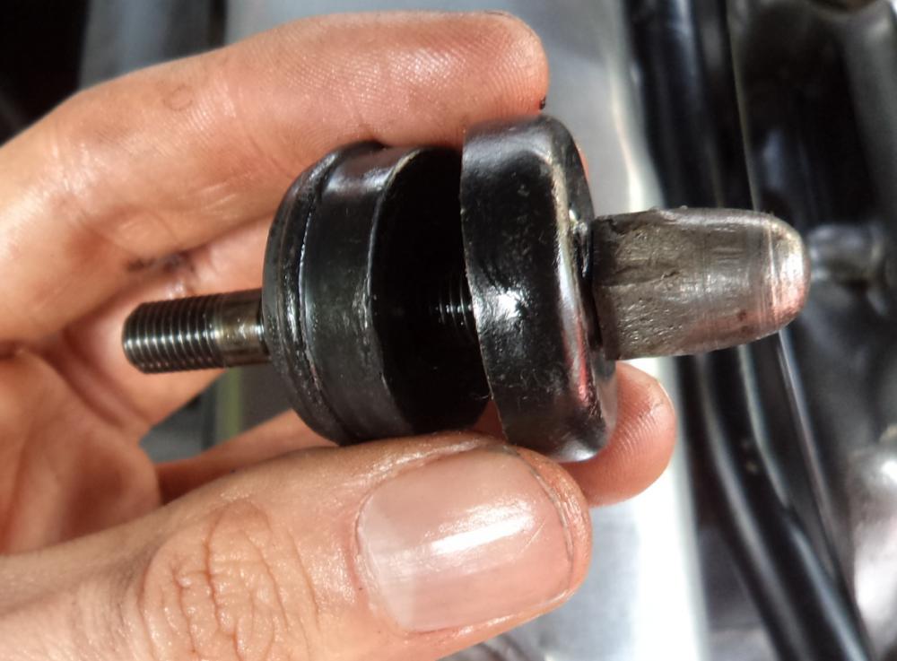
Before refitting the cam cover, check to see if the rubber spacers are crushed or perished.
Refit the cover on the cork gasket using a little silicon sealant for better sealing. Nitrile rubber alternatives are now available and maintain a much better seal but cannot be reused as many times. Tighten down the three nuts until the cover is just hand tight. The rubber spacers should maintain the seal when under compression, so do not overtighten to avoid damaging the gasket.
Part 2 – Crankshaft Bearings
 The 2000/2200 engine is a strong and durable engine design. However, it has a surprisingly short life expectancy for its crankshaft bearings. The exact reason is difficult to prove. Part of the original design brief for the 2000 was to offer comparable levels of performance to a much larger luxury saloon. As such, lightness was key to the engine design, and as a result the cylinder block is an unusual ‘skeletal’ design with huge windows cast into the sides, covered in thin steel plates – a regular source of leakage as they corrode. It is possible that a consequence of this was a loss of some torsional rigidity in the block. This theory is backed by the use of a deep, thick-walled, aluminium alloy sump tied through to the gearbox – a cost justified only by adding vital torsional rigidity. In practice poor rigidity of the crank area would lead to premature bearing wear and perceived roughness of running – both features of the Rover engine. Another theory, backed up by the wear pattern on the shell bearings, indicate oil starvation on starting. The four cylinder has a very high mounted oil pump which has to suck the oil up several inches from the sump before forcing it through the galleries. This causes premature wear through a hammer blow effect on the crankshaft bearings through a slow build up of oil flow and pressure.
The wear rate seems to vary. Whether it be as a result of high load on a flexible block, or frequent cold starts after long periods of lay-up, it is also impossible to rule out that poorly observed service intervals and incorrect oil grades could have also accelerated wear over the 40 or so years of a car’s life. It only takes one piece of grit to wear a shell down to the copper in just a few hundred miles. Whatever the cause, modern consensus regards the bearing shells as consumable service items, and common experience is currently suggesting that life expectancy is between 40,000 and 60,000 miles for con rods and 50,000 and 80,000 for mains.
 Neglecting the bearings causes low oil pressure at idle when the engine is very hot. This causes further premature wear on the crank, and if left unattended can ultimately result in a con rod breaking with corresponding engine damage (an extremely rare but known occurrence on worn engines driven very hard). Low oil pressure is also the primary cause of a lumpy idle and tinkling timing chains when the engine is warm, as the oil pressure is not sufficient to maintain optimum tension of the chains. Owners of Series 2 TC models, or other models with aftermarket oil pressure gauges, can see the oil pressure drop to about 35-45 psi during idle and pick up to 50-60 psi during normal driving. These symptoms occur well before any characteristic bottom end ‘rumble’ develops. Bearing shells in good order should be able to maintain 50+ psi of oil pressure at all times.
Fortunately, replacing the bearing shells it is not a difficult job and can be performed with the engine in-situ (contrary to the workshop manual) with a very basic tool kit…… and a wooden lolly stick!
The Tools and parts you’ll need
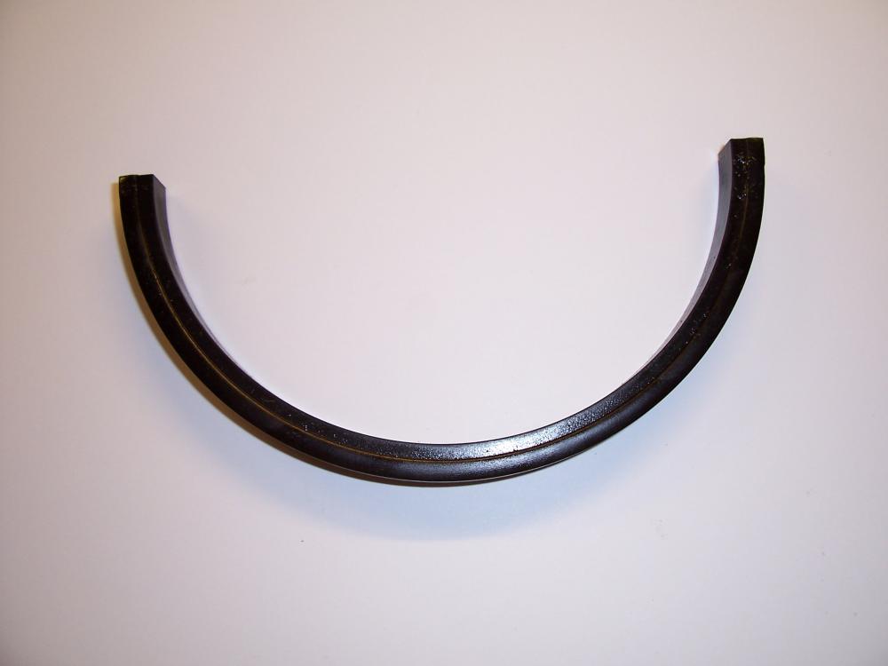
Aside from basic hand tools, you will also need a 3mm allen key, accurate torque wrench and a wooden lolly stick to complete this job. You will also need Hylomar (or similar) flexible gasket paste, Graphogen (or similar) engine assembly grease, a new O-ring for the internal oil pick-up pipe, a new rubber sump seal for the No 5 bearing cap and a set of main and big end bearing shells in the correct size for your crank. It is a wise move, but not imperative, to fit a new set of crank thrust washers as well. Fresh engine oil and a new oil filter will also be needed.
Identifying the bearing shells you need
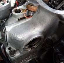
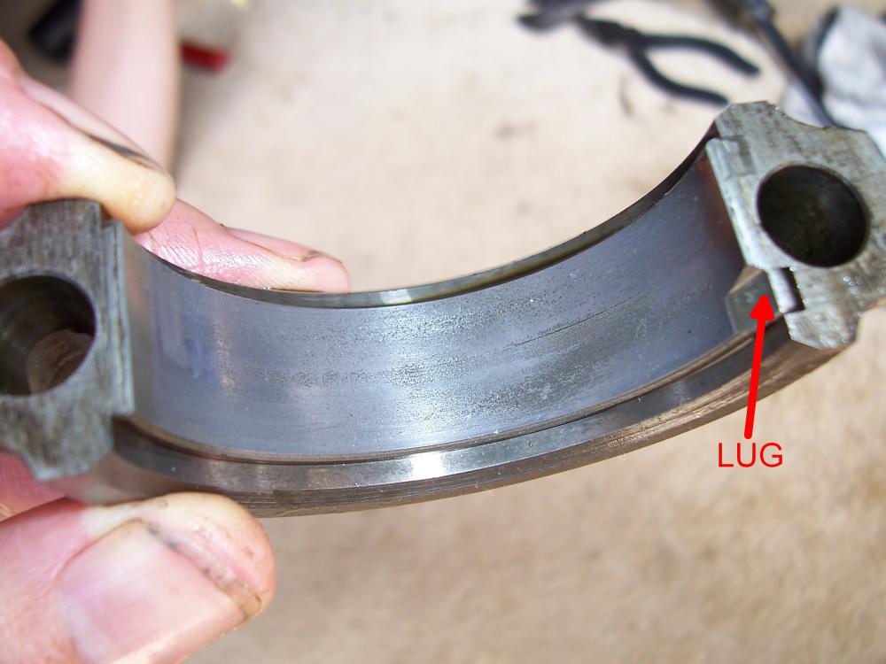
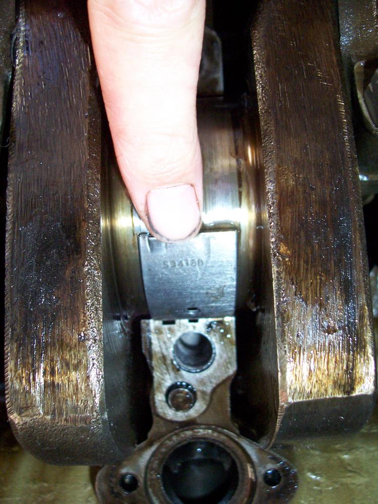
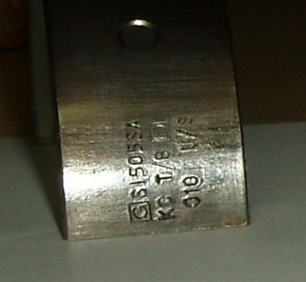 For early Series 1 2000 SC manual models, look at the suffix letter on the engine number. Engines up to suffix F will need main bearings M5211. From suffix G onwards – and for all other four-cylinder models – you will need M5246. There was a succession of minor changes to the 2000 engine to refine the design in its first years of production, and the earlier cars need main shells with a plain centre bearing. All models use B4434 for the con rods bearings. If you don’t know the history of your car, you should remove one of each to find out if you have standard or undersized bearings (if the crank has been re-ground) so that you can buy them appropriately. Bearing sizes are stamped into the shell. They should be stamped “STD” for standard, or usually three digits e.g. 010, 020 etc for thousandths of an inch that the journal has been ground (see right).
Remanufactured bearing shells in standard and plus-sizes are now readily available from most P6 parts suppliers. Original old stock items do come up occasionally on eBay, but expect difficulty sourcing standard size big end bearings – mains are easier to come by.
When you have your bearings, leave them to soak in engine oil overnight or until required, they are made from white-metalled sintered phosphor bronze which is porous and will absorb the oil.
This article assumes that your crank will be in good order with no need for a regrind. Clearly, if you remove the bearing caps and it is evident that the crank is scored, it will be necessary to remove the crank for regrinding (after removing the engine). Regular changes to the bearing shells will reduce this need and drastically increase the life expectancy of the engine.
Replacing the bearing shells
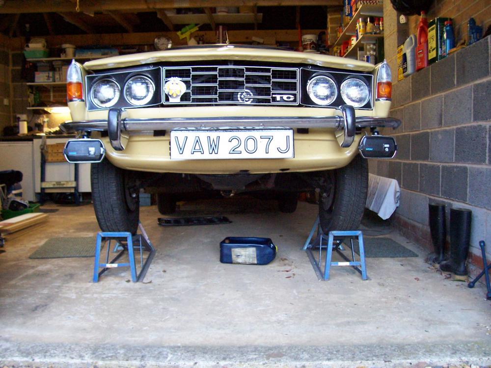
With the car appropriately supported, drain the oil, remove the spark plugs, remove the fan belt and remove the sump – noting which holes use the longer bolts.
Big end bearings
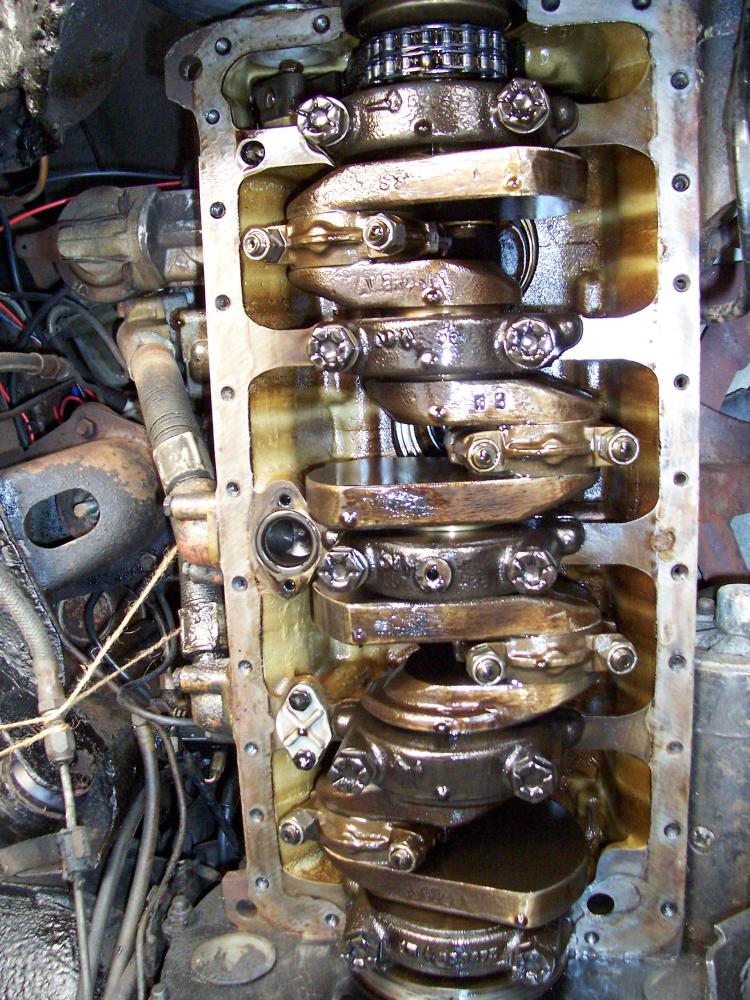
Rotate the crankshaft pulley until the number 1 big end (number 1 piston, nearest the radiator) is accessible (just past bottom dead centre so that the top shell can be easily accessed), remove the big end bolts and remove the bearing cap. [Fig 1, below] Slide the bearing out of the bearing cap – it comes out lug first – and then slide a new bearing in place the same way the old one came out until the lug slots home [Fig 2]. Push the piston up the cylinder and lift the con-rod over the top of the crank until the top bearing shell is accessible [Fig 3]. Replace the top bearing shell in the same way. Cover both bearing surfaces in an engine assembly compound such as Graphogen and refit making sure that the top and bottom bearings go together lug-to-lug. Take care to make sure that the bolts are properly located in the con rod. They have eccentric heads and you may need to rotate them until they seat properly in the shoulder of the con rod. Apply some thread lock to the studs, put the nuts back on and tighten to a torque of 30 lbft. Repeat for the other 3 big ends.
Main bearings
First make sure that the crankshaft is free to turn without any tension on it. Slacken off the bottom timing chain tensioner. Use an 1/8 inch (3mm) Allen key and turn clockwise. The chain puts too much tension on the crank, not letting it drop enough to get the old bearings out easily.
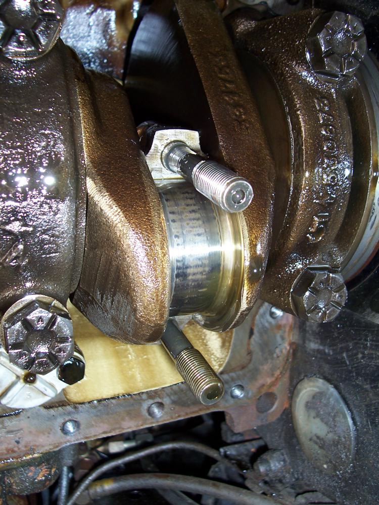
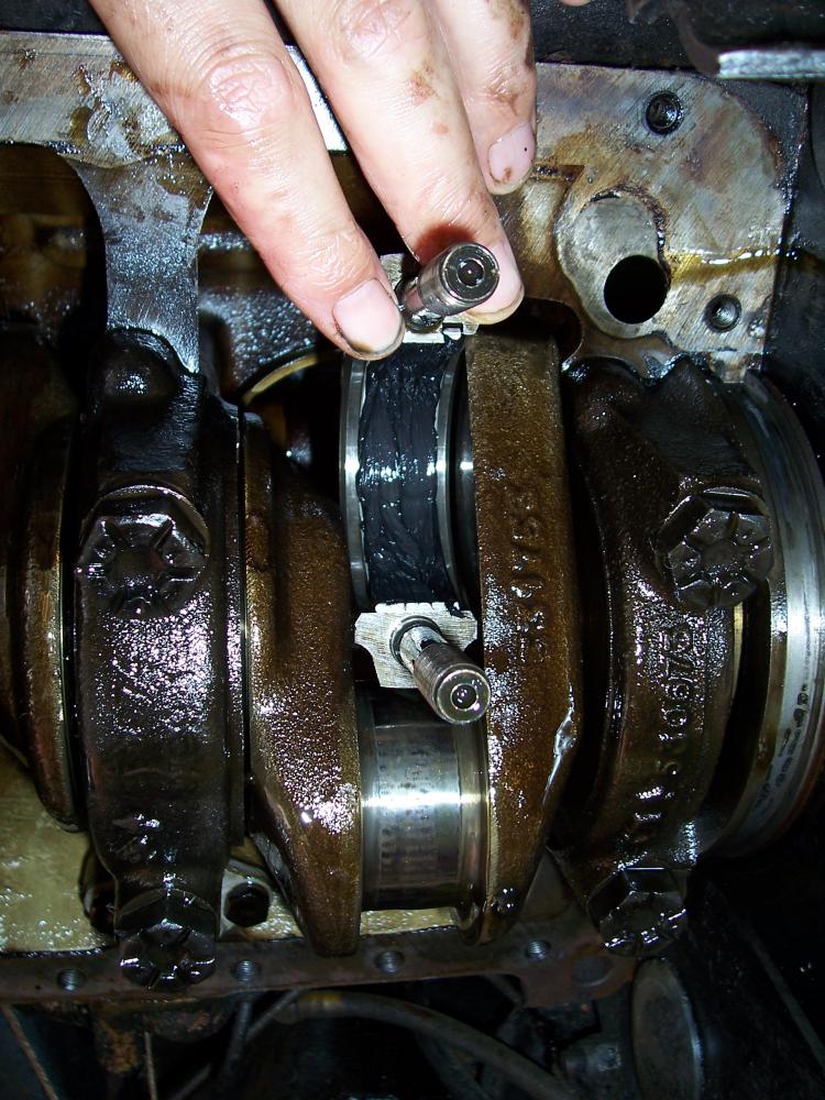
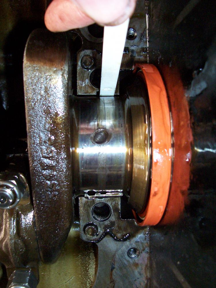
The main bearing caps are all numbered 1 to 5 and each cap has an arrow on it pointing to the front of the engine. [Fig 1, below] They also have locating pins so that you can’t put them back on the wrong way. Remove all bearing caps. Number 5 will probably be a bit stiff and need tapping with a rubber hammer to free up, it covers the rear crank lip seal and also the rubber sump seal [Fig 2]. The latter should be replaced while it is off. Now give the crank a wiggle to free it up a bit. You should be able to see the top main bearing shells either side of the crank, one side is plain ended, the other has a lug, just like the big ends. Using a lolly stick, push on the plain side and the bearing should slide over the crank [Fig 3]. When enough has been pushed round, pull it all the way round until it is underneath the crank and remove. Smother a new bearing in oil (no assembly compound on this one or you wont be able to put it back) and place under the crank (plain end next to the notch) and slide round over the crank until the lug sits in its notch [Fig 4]. Repeat for all other top main bearings. If number 1 causes you any trouble, push the crank to the side – it is still under some tension from the timing chain which can make pushing the old bearing out a bit harder.
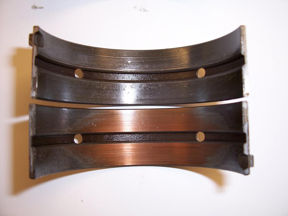
Bearing cap 4 contains the crank thrust washers. These are slid in either side of the main bearing. At this stage it is worth sliding them out to inspect for wear. They should be a copper colour. If they are showing significant signs of wear (again available in standard or plus-sizes), you should replace them ensuring that the copper side face outwards against the crank webs, with the steel beds facing inwards against the bearing shell.
Replace the bottom shells in the bearing caps exactly as before with the big ends and smother them in engine assembly compound. Refit in the correct order and torque up to 65 lbft.
Now turn the engine over by hand and ensure a nice clean, smooth operation with nothing binding. Don’t forget to re-apply tension to the bottom chain tensioner by turning the Allen key clockwise. Change the sump internal oil filter O-ring for a new one, refit the pick-up pipe, and refit the sump with a smear of Hylomar. Put all bolts in fairly loosely and then torque up the bellhousing/sump bolts to 25 lbft before tightening everything else up.
Refill with a good quality 20/50 engine oil and a new oil filter. Fire up the engine and allow it to idle slowly until the oil pressure builds. Run it for a few minutes to ensure pressurized oil has reached all parts of the engine. Recheck the oil level and top up if necessary.
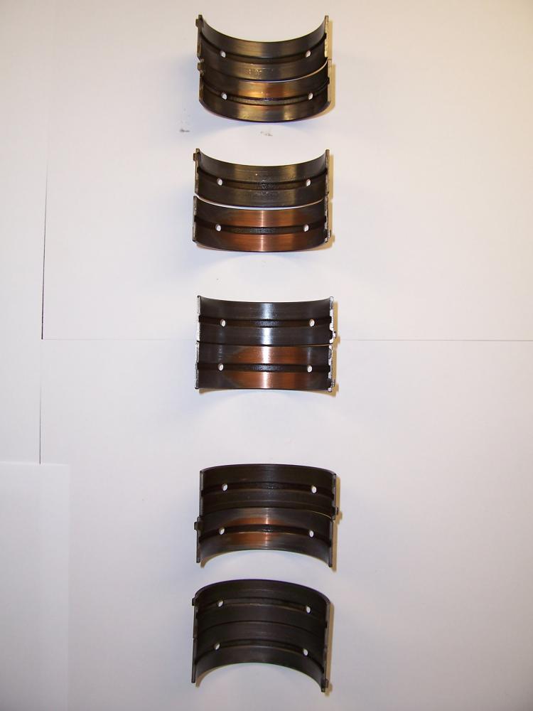
Main bearing shells worn down to the copper after 38 years and just 54,000 miles
Words: Part 1 – Michael Allen
Part 2 – Brian Humphreys
Originally published in Driving Force magazine
October / December 2013